

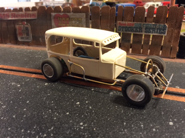
I started work on another car today and I thought it was high time I showed how I do it. This is not by any means, the only way to do this. It’s just my way. So if you’re interested in building a jalopy like the ones we’ve been doing lately, pull up a chair and have a look.
I start out by setting up my jig. I use the Razor Jig just because I like it. You can use whatever building apparatus that you’re comfortable with. For the High Boy Model A’s, I set the wheelbase stock at 104″. Which works out to 3 1/4″ in 1/32 scale.
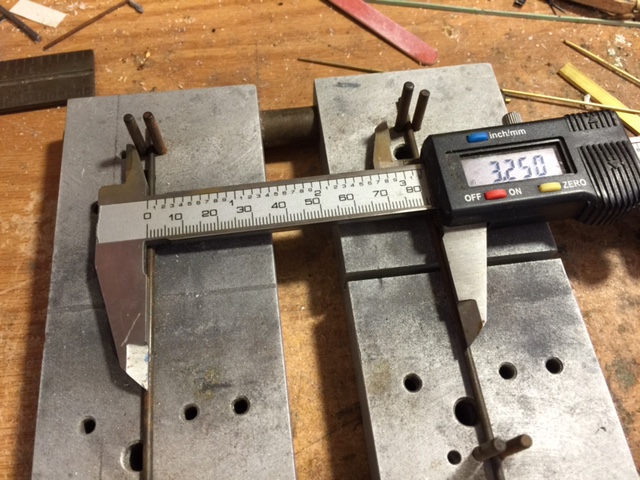
This might sound rudimentary to some but It’s where we start, so I’ve shown it.
Next, I cut the stock I’m going to use for the chassis rails. In this case I use K&S part #8150. It’s 3/32″ square tubing cut to 4 1/2″ lengths. The rear crossmember is 1″ and the front one is 3/4″ of the same tubing.
After they’re cut and the ends dressed, I put one of the build axles in the jig to use to square up the chassis against. I then arrange the pieces on the jig to be soldered.
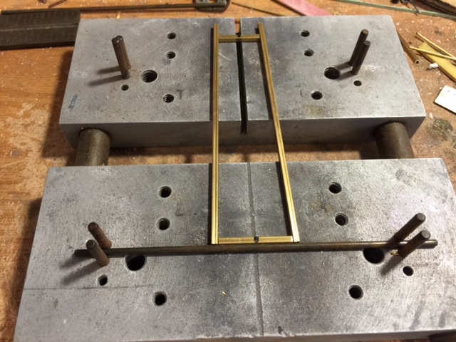
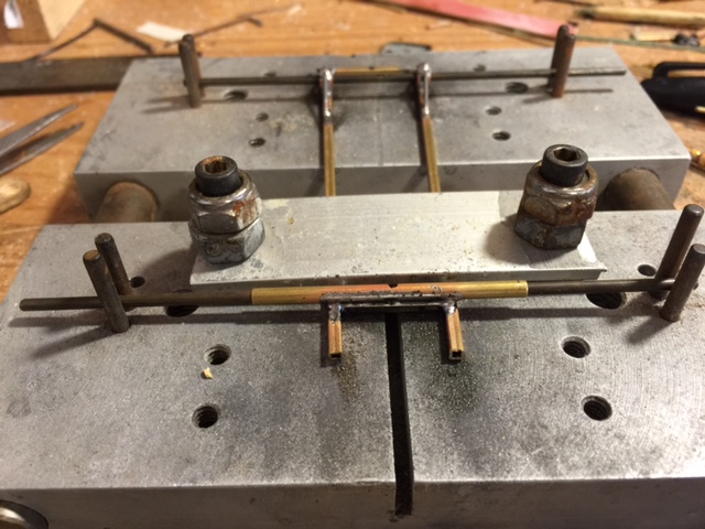
I made a simple clamp system for my jig. It works good for me. I have two of these straps that I use to secure things to the jig bed. It works perfect for me.
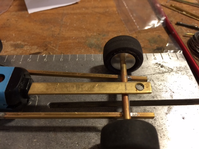
Once the pieces are clamped down, I mark out the wheelbase on the side rails of the chassis. You can see the two black marks on the right rail in the picture. That is where my axles will eventually go. For a High Boy car, I put the front crossmember right where the axle will be. Just like the 1:1 car.
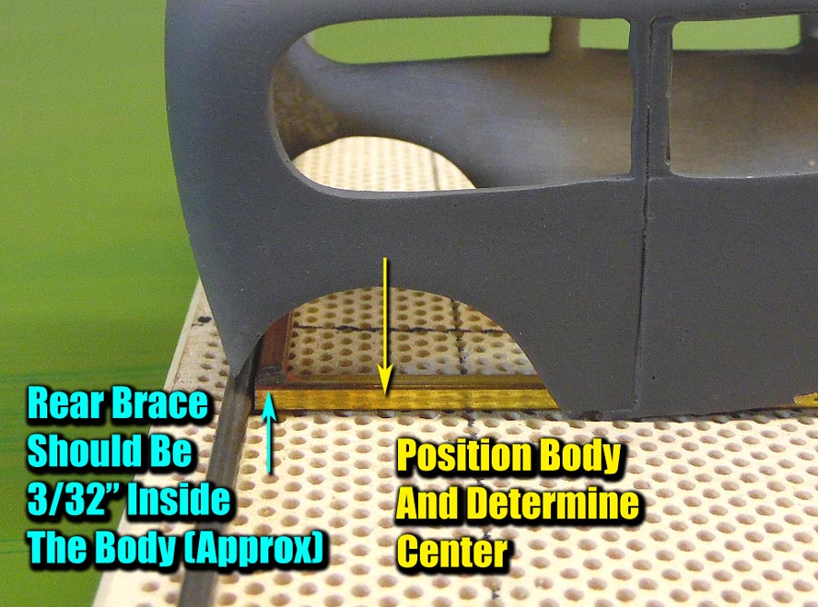
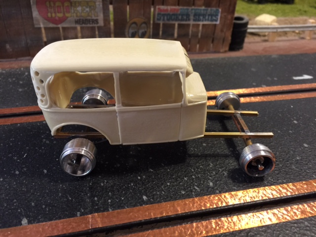
To find my spot for the rear axle I place the body over the frame where the rear of the body just overhangs slightly. Then I find the center by looking at the wheel well. Not a perfect science here, but it works. Now I can mark my area for the rear bushings and measure from there to mark my front.
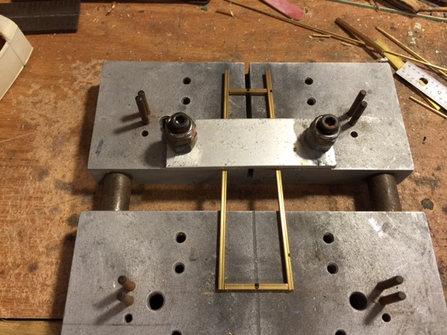
After you have your clamp in place, go ahead and solder all the joints.
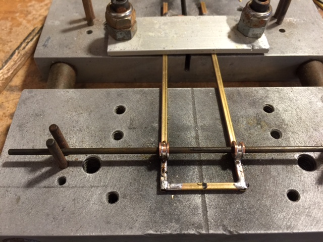
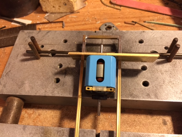
Now that the joints are all soldered, remove the clamp and position the chassis in the jig so you you can put the axles on. I slid the chassis back and put the axles in the pins to double check the wheelbase measurement. Then I put a pair of SCC bronze bushings on the axle. They are part #CP-01000.
Now that you have the axle/bushings where you want them, go ahead and solder the bushings to the chassis.
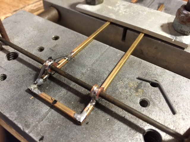
Next we’re going to fabricate some supports for the bushings. I use K&S music wire in .047 diameter. Part #502. Just bend it like the one shown there on the right and cut them to length. Then place the bend in the groove on the bushing, with the ends resting on the chassis. Then solder it down. Now those bushings aren’t going anywhere.
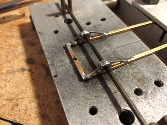
Here’s what it will look like with both of them soldered on.
Now we move to the front axle. I used a 2″ piece of K&S 1/8″ tubing. Part #1145. It has an inside diameter of 3/32″ for the axle. Just slide it over your setup axle and place it in the pins on top of the chassis. It should be right on top of the front crossmember if you did your measuring correctly. Once it’s setup on there, solder it on.
At this point, you can unclamp your work and clean it up. I just take mine to the sink and use warm water with soap and a brush. That cleans all the flux off so it’s not all messy. Now you have a nice, square, basic chassis to build on.
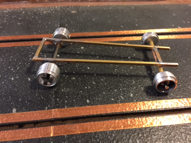
You’ll notice that the axles are now on the [b][i]bottom[/i][/b] of the chassis. In essence, we have been building the chassis upside down. For a High Boy car, I like the axles in this position because it sets the car up higher. If you really wanted to, you could leave the chassis the other way and the car would be a lot lower to the ground.
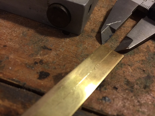
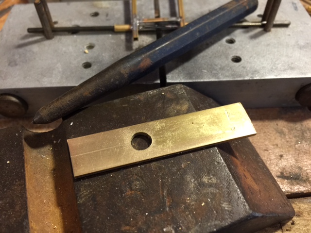
Next up, we’re doing the motor mount bulkhead. I use a piece of K&S 1/2″x1/8″ brass for the bulkhead. I don’t have the part # handy for this one. We need to find the center of it for drilling. So set your caliper for 1/4″ (.250) and use the sharp jaw to scribe a line down the center of the brass strap.
Now we need to drill a hole for the pinion to go through. The boss on the end of the motor is 1/4″, so center punch on the scribed line and drill a 1/4″ hole. I leave plenty of extra room on either side so we can trim it to size later.
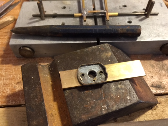
Now we need to drill the motor mount holes. What I do is use the cut off end of an old motor for a template. Just set it on the strap and mark the holes with a pencil.
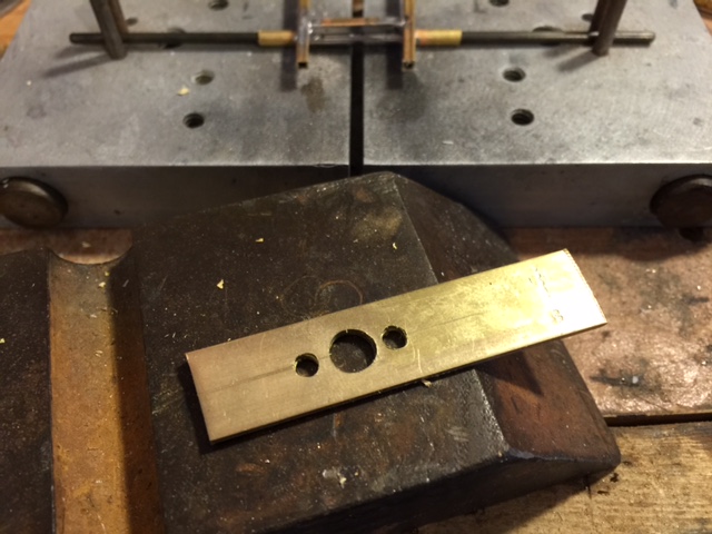
Then just center punch the marks and drill a 9/64″ hole for each screw. When you’re done, it will look like this.
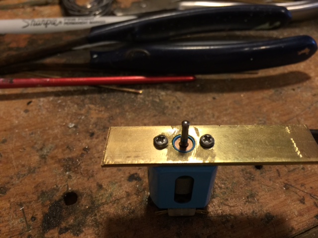
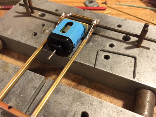
It will look like this after the motor is mounted. I use SCC motor screws. Part #MTRHW
Now we can set it up on the chassis and put it in the position we want.
Then mark the strap and cut it to fit.

Here’s what it looks like with the motor in. Now we can bend up a motor support. To the right of the chassis there, is the support. it is made out of that same piece of .047 wire. Make your bends and cut it to fit.
It should look like this.
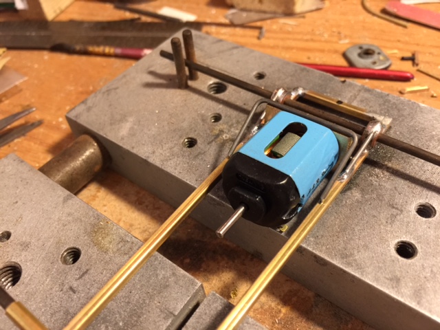
When you’re happy with it, solder it in. I do all my motors this way and they’re sturdy as they can be.
Now we’re ready for the guide tongue.
You will need a piece of K&S 1/4″x1/8″ strap to fashion the guide tongue from. Find the center, punch it and drill a hole for the guide. The posts vary in size but 9/64″ is a good start point. If you have to, you can use a reamer and open it up a bit. Once you have that made, lay it on the chassis and locate where you want your guide to sit. I like mine just ahead of the axle, so I put a mark right behind it to mark my bend.
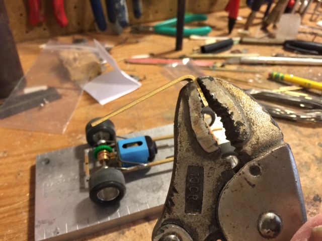
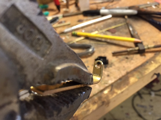
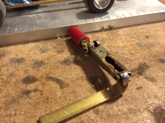
Now that you know where the bend will be, put the strap in a vise or like I did, in my Vise Grips. Set it up so the line is even with the jaws and bend it over at a right angle. It will look like this.
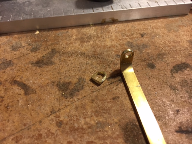
I like to double stack the end that supports the guide flag. So you will need to make a small piece to solder on the end. I just used a piece of scrap from the same strap. Do the same thing, find the center, punch it and drill the hole.

Now that you have these two pieces made, you will need to round them off so the guide will turn. I just hold them in the Vise Grips and use a sanding drum on my Dremel to do this. The parts will look like this.
Then cut the little filler piece off to fit on the end of the tongue. It should like like this.
Now we need to solder them together. Just stack them up and hold with an alligator clip and solder them together like this.
After it cools, you can dress them a little with the Dremel and run the reamer through the hole. Or use a round file if you don’t have a reamer. Just to clean the hole up a bit so it doesn’t bind or cut into the guide post.
Now you should have an assembly that looks like this. Go ahead and put your braids into your guide so we can set the depth when we solder the tongue on.
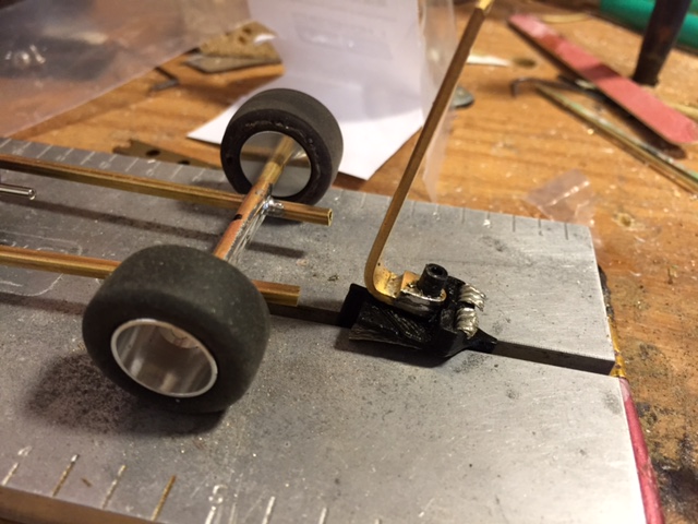
To set the depth properly, you’ll need the wheels and tires on the chassis. use the ones you’ll be running on the car or it will change if you use a different size.
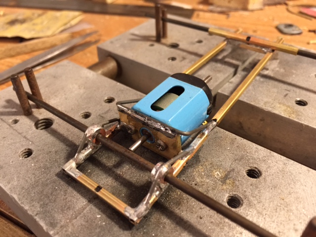
And now, all that’s left is to solder the guide tongue on to the chassis. Just place the bracket behind the axle and push the guide down flush into the slot. Then hit it with your solder. Once it cools, cut the excess strap off and you’re done!
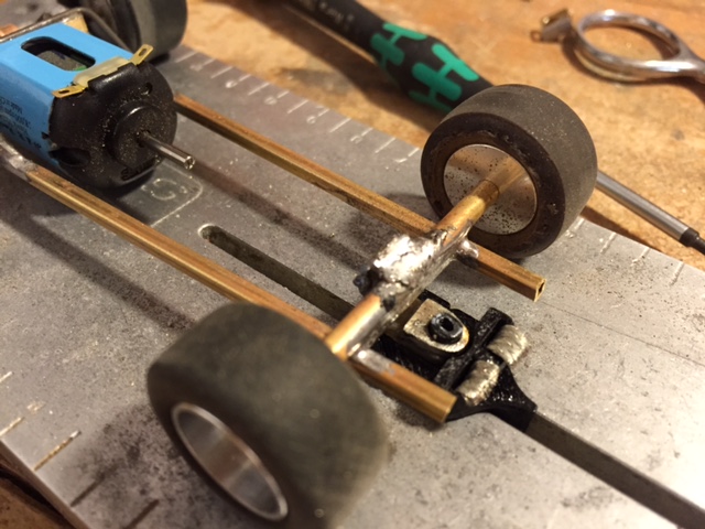
All that’s left is to solder your wires on and take it for a test run.
So there you have it, a running basic chassis that you can build on to make whatever car you want. Bend up some nerf bars and solder them on and away you go! Hope you guys found this helpful. Any questions, please don’t hesitate to ask!
-Shotgun Dave
