First off, materials:
I use .040†thick brass for my brackets, as I like the extra strength and the little bit of extra weight that this thickness provides in comparison to the .032’ material that most commercial brackets are made from. I buy scrap pieces from the “Project Bin†at a company called Industrial Metal Supply - they are conveniently located a short drive from my house, and they also have a very well-stocked K&S metal selection, so most of my building materials are bought there.
I cut strips of brass ½†wide off these scraps, using my band saw. It has an 18TPI blade so it rips through the brass pretty easily.
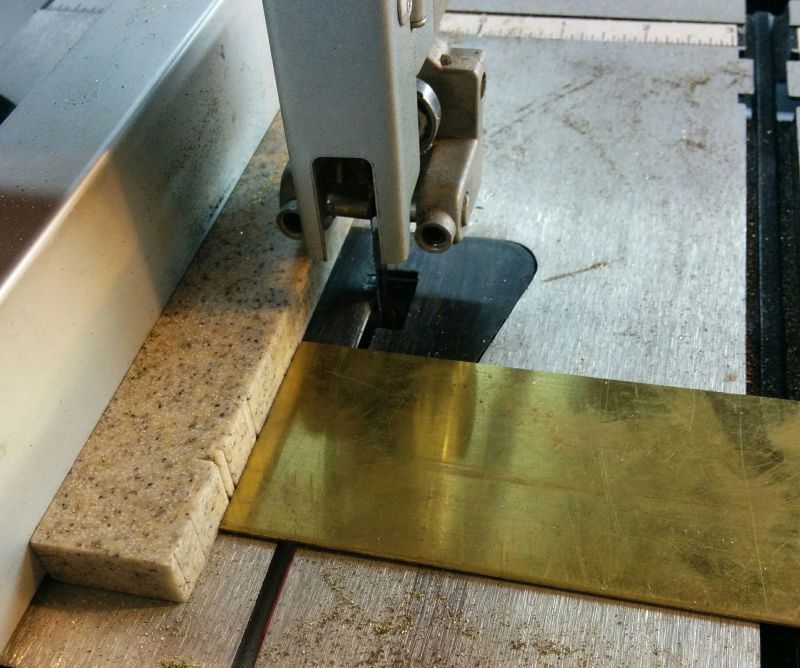
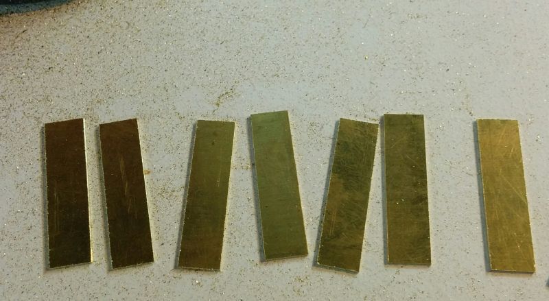
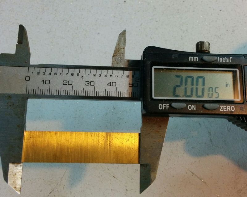
What I’m looking for at the end of this is a number of pieces all ½†wide and a little bit over 2†long. I don’t try to cut too close to the 2†limit on the band saw, I leave a little extra always. You will see why soon.
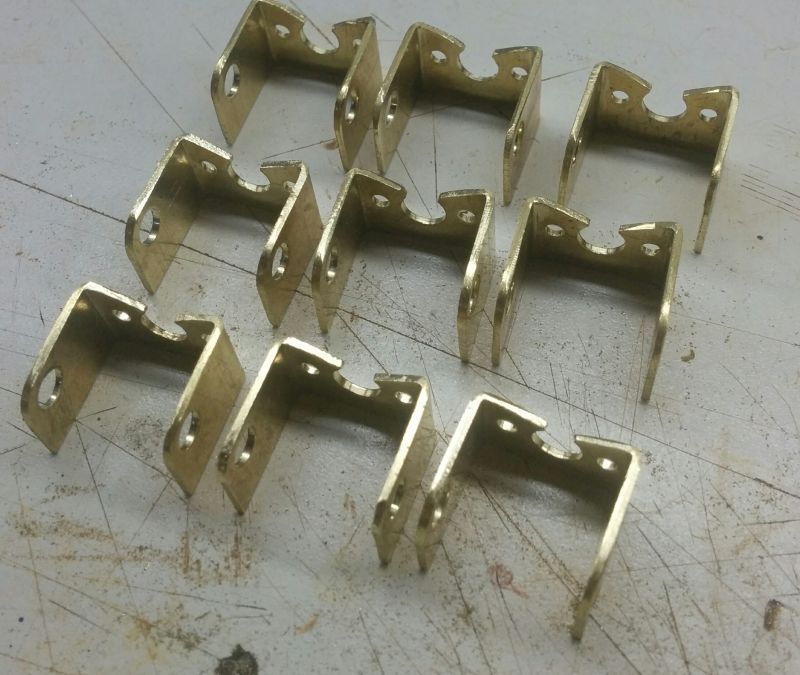
I also don’t usually make one bracket at a time, the process is quite long and it makes sense to make a bunch at once. Plus, since it’s such a manual process, they don’t all come out right!
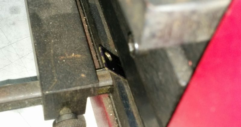
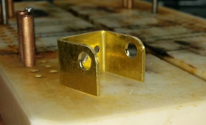
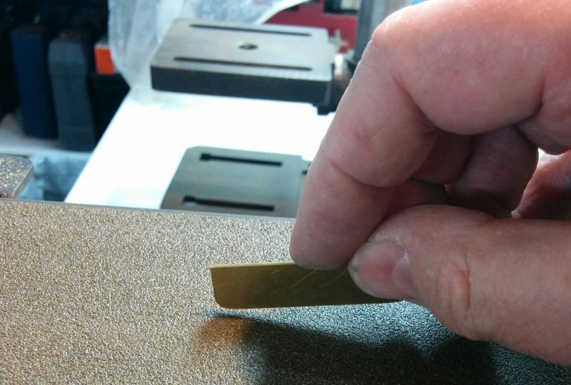
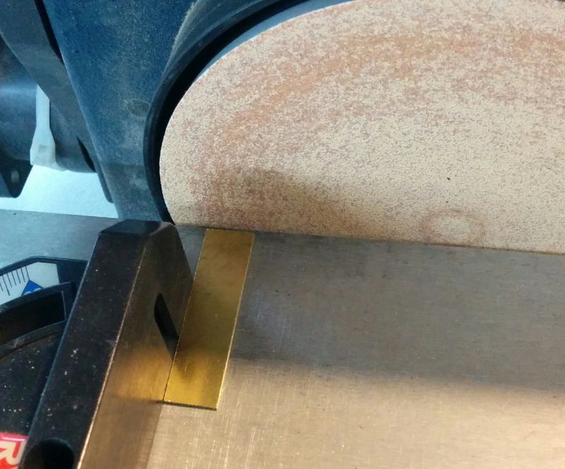
So now I have the blanks, it’s time for some more precision work. I use a belt sander to smooth the long edges on the strips, then I go to the disc sander to finish the length. After a lot of experimenting, I have worked out settings on my bending brake that will give me a 3/4†wide bracket from a 2†long strip, so the closer the strips are to that measurement, the more consistent the bracket widths will be. Also, it is important that the ends of the strip are very square to the long edges so that the brackets when bent are nicely flat and square.
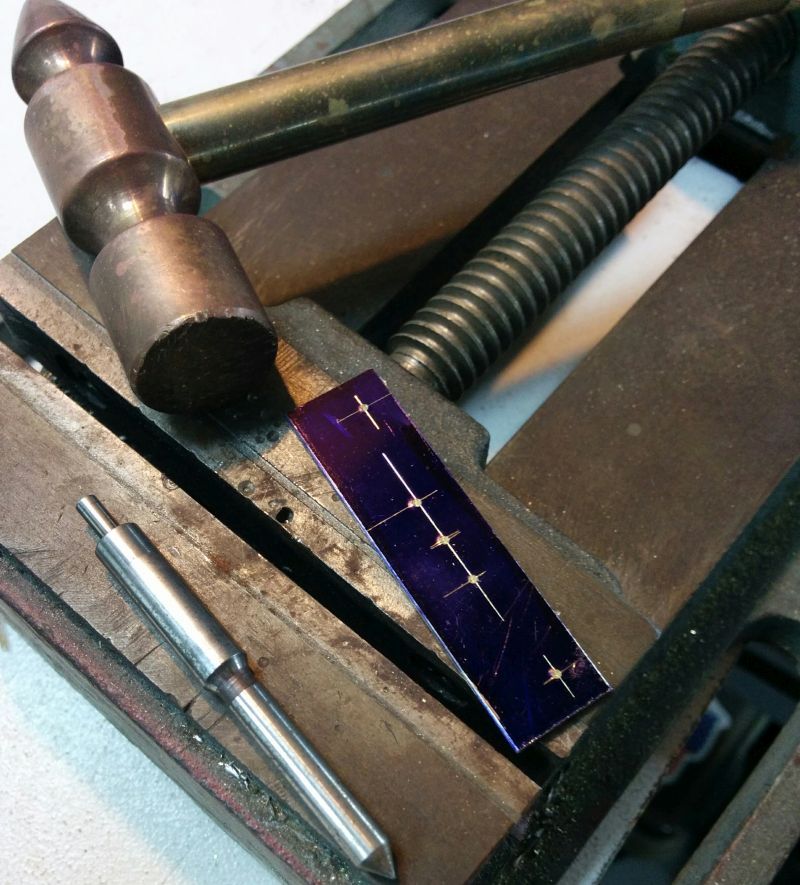
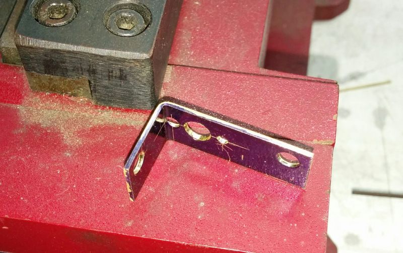
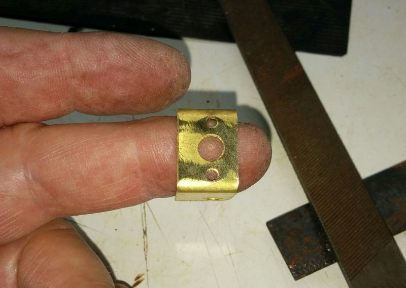
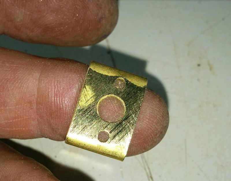
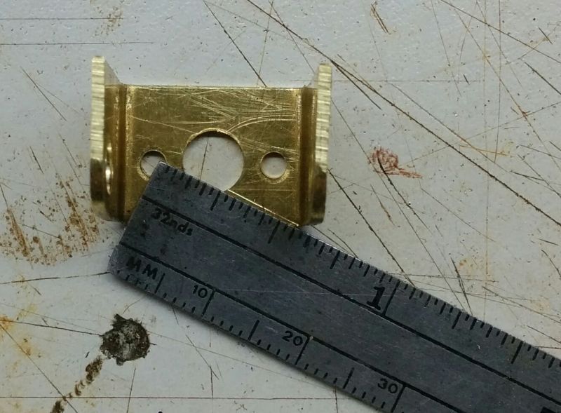
Now it’s time to mark the dimensions. I “blued†one of the strips so the markings come out clearly on a photo, but generally I just scribe them onto the plain brass with the sharp edge of my digital calipers. Here’s the drawing and the item:
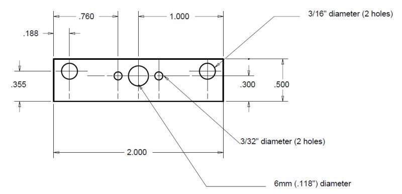
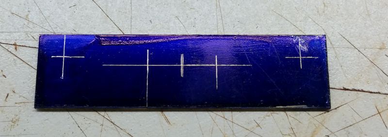
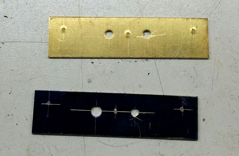
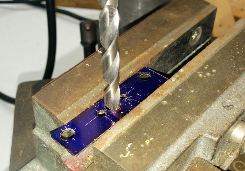
You’ll notice there’s a double mark on the center hole. I always mark that one from both edges of the bracket to be sure that I have the motor perfectly centered. When I center punch the hole, I estimate the spot between the two lines.
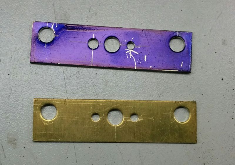
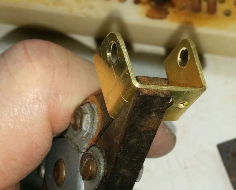
You will also notice that in the drawing for this batch of brackets, the axle holes are on a different center line to the motor holes. These brackets are destined for 1/24 scale Retro cars, where we run 13/16 rear tires and a .050" clearance, so the offset between the axle and the motor holes allows the bracket and motor to sit flat in the frame. The gears we use accommodate this without issue. Obviously it is just as easy to make brackets with no offset or a different offset, like the .040" that would be used for the Slot.it offset gears.
Continued in the next post.